Week 7, Assignment 7
Computer Controlled Machining
Video - Week Seven, Lecture Seven
Goal
The goal for this week assignment is to make something big, so obviously it’s time for machining on Shopbot a large format CNC machine. This week I will be converting a CAD drawing into the real life object.
Introduction:
This week’s Computer Cutting Machining page includes various CNC machines like Roland, Shopbot, Onsrud, etc. which is used to make machines from a machine within FabLab from several processes. I have Shopbot in my Lab which I will be using for this assignment. Shpbot is a 3 axis CNC machine.
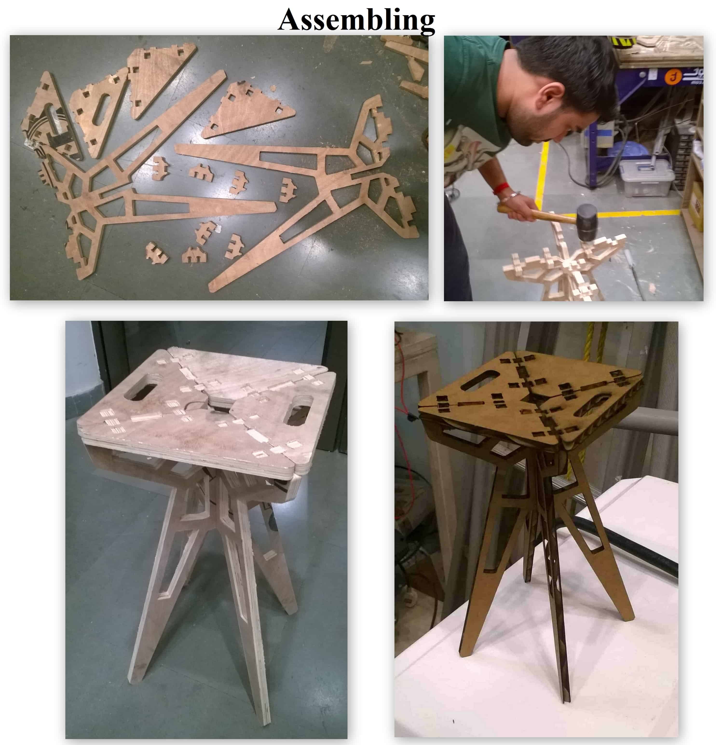
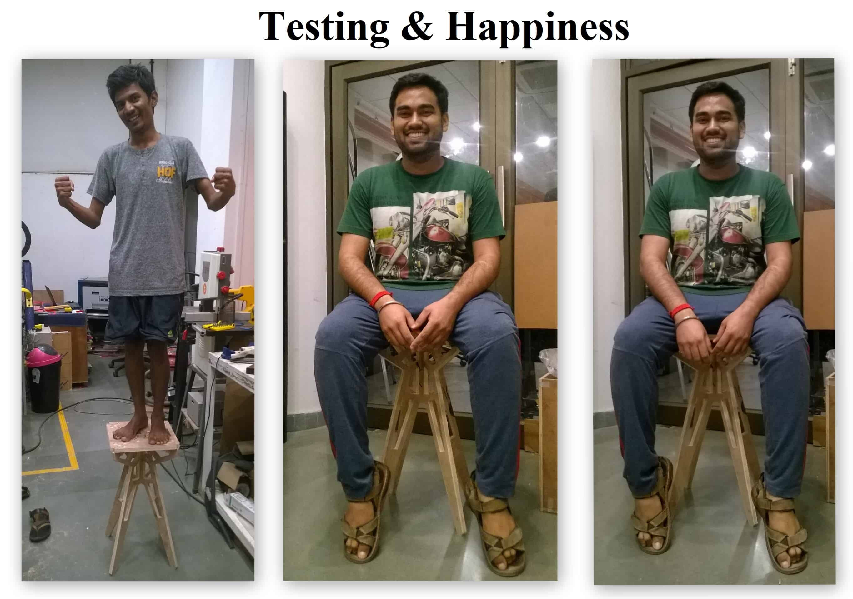
The Computer Numeric Control machine (CNC) is the machine which takes the input of design files and the machine able material like wood, wax, acrylic, composites, the output will be the fully designed files which can be assembled to make the usable products. So I Decided to make something that can be used by anyone in my Lab.
So again in this assignment I need to design, cut and assemble the object I create. I used Catia to make the design for my thing, I used the software, V-Carve for making toolpath.
So, first to begin with I google for some good chairs and stools that I can find and selected one and make its design for further process.
Designing:
Before starting to design I was making sure about all the dimensions which I am suppose to keep, so for that I measured some available stool’s height and width which was about 450 mm by 400 mm, so as I was making a Stool I decided to increase height a bit by 200 mm and then accordingly started working on the design. I then decided to use 18 mm thick plywood so that it should be enough to sustain any weight on it.
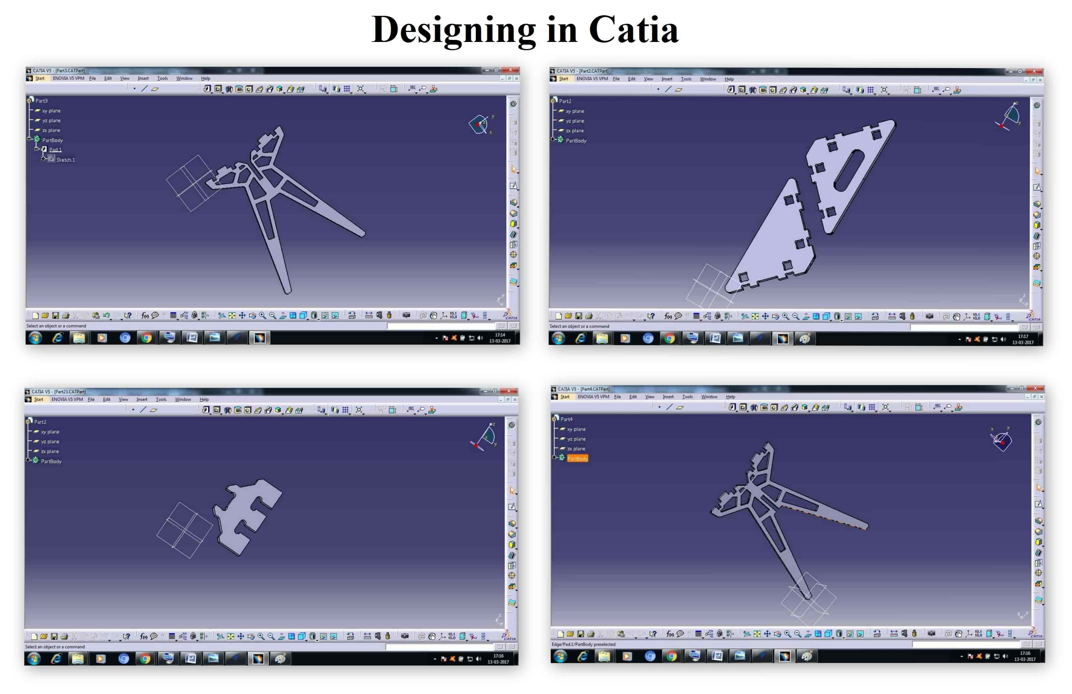
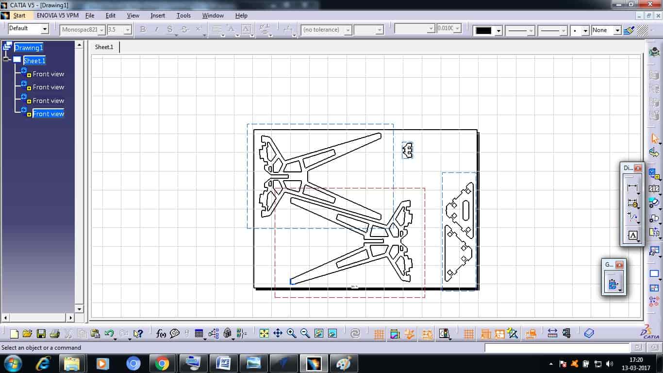
I then Exported my 3D Part file to 2D Drafting format and then exported it to .DXF format which is opened in almost any software for further use.
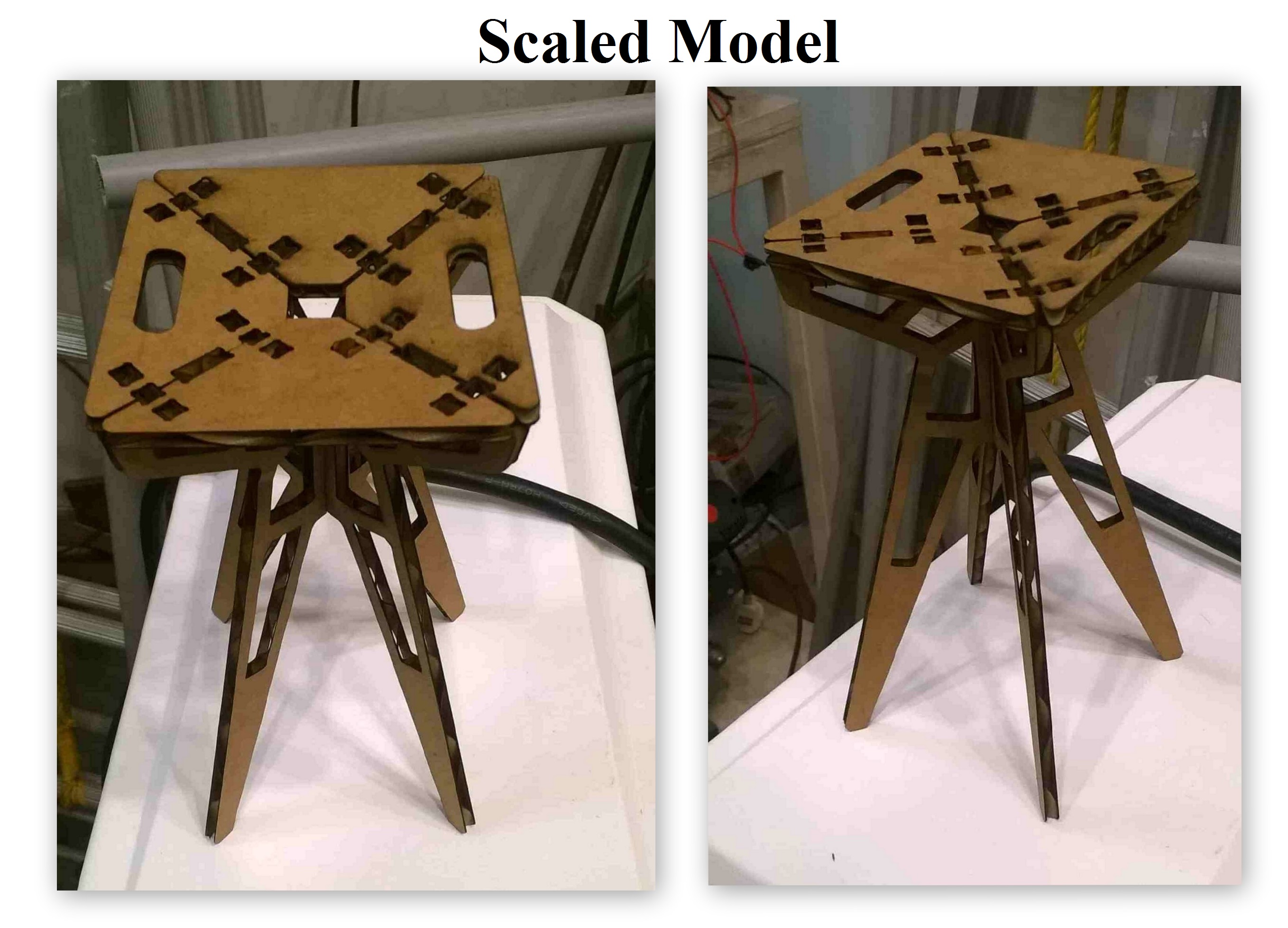
Scaled Model:
Its always better to make the scaled model of the thing that I was intended to make. I then opened my .DXF file using CorelDraw to scale them down and cut it on a Card Board Sheet using Laser Cutter. The Scaled Model can be seen below, this scaled model worked perfectly well which proved that I can easily move forward on Real cutting now on ShopBot.
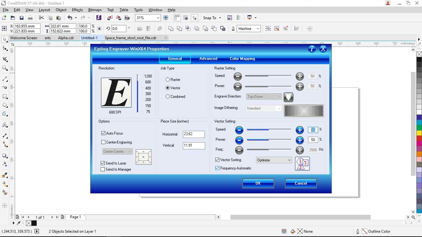
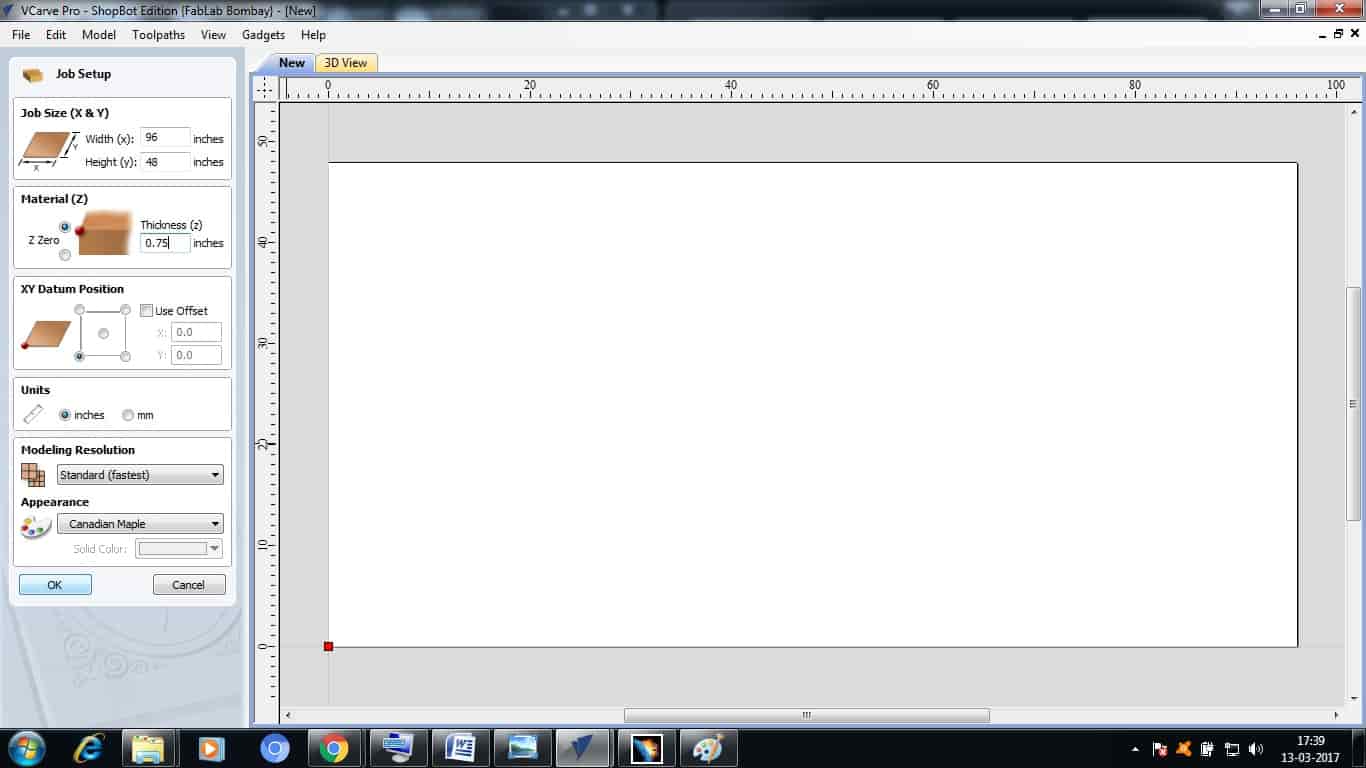
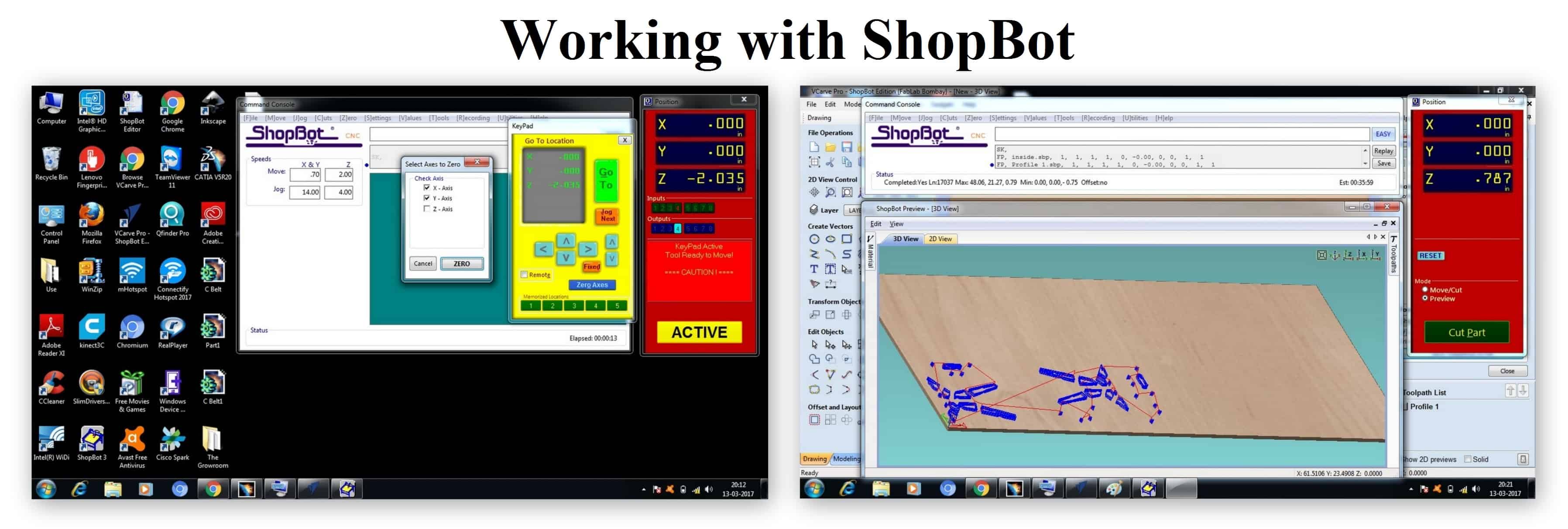
VCarvePro:
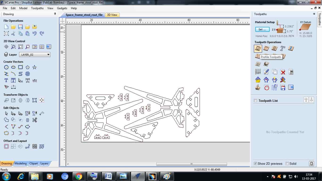
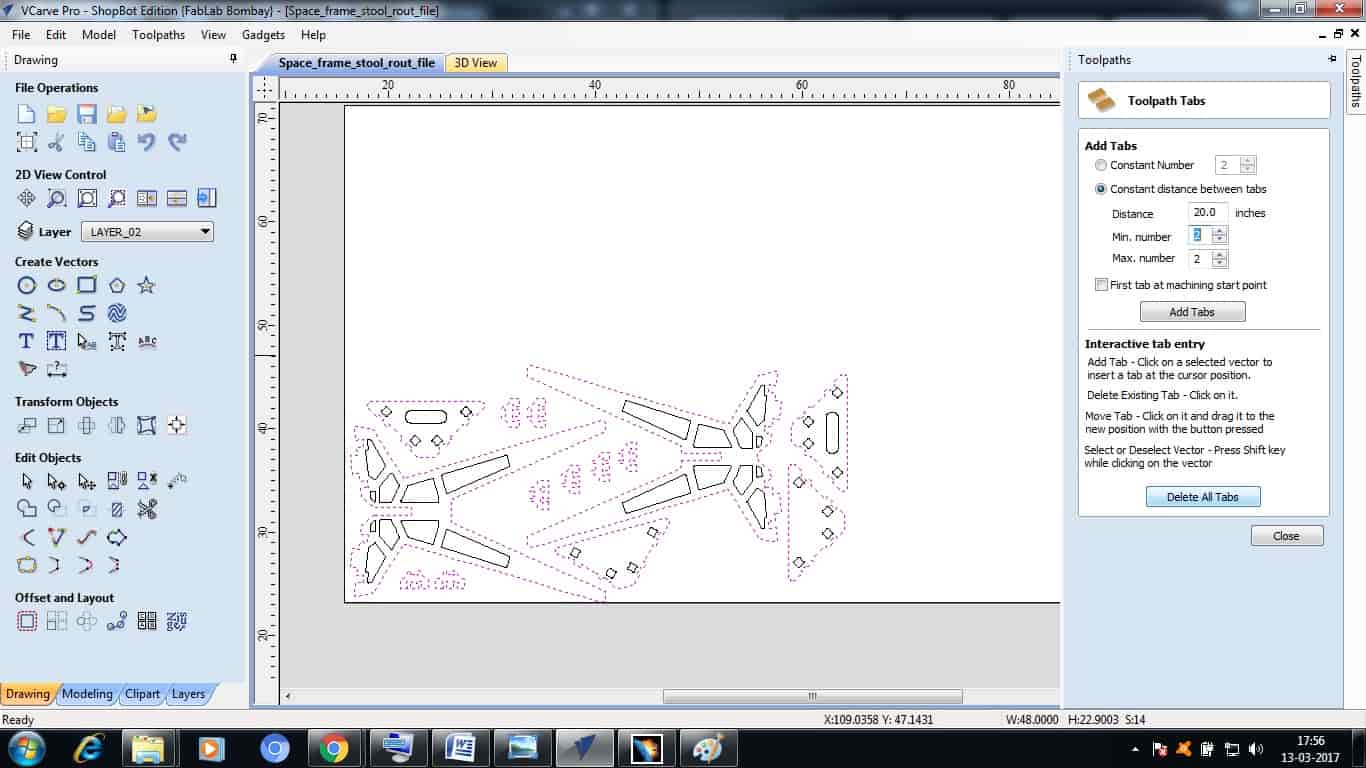
VCarve Pro V8.0 ShopBot Edition is used to communicate with ShopBot for doing various operations. So after finishing with designing I opened my .DXF format 2D design file in VCarve, after opening first thing which it asks is the Bed Size so my ShopBot bed size is of 96 inches x 48 inches, which I mensioned and do make sure to check what format are you using inches or mm otherwise it give a way lot problem while cutting.
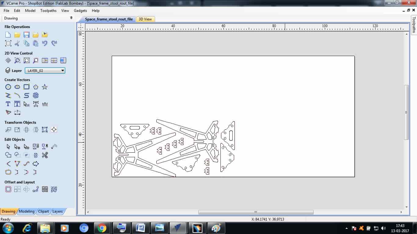
So, after all that settings my file is now displayed on my work area shown in VCarve. VCarve have some Editing options also which if required can be used. So by using few options I then arranged my File accordingly and Increased few parts as they were need more.
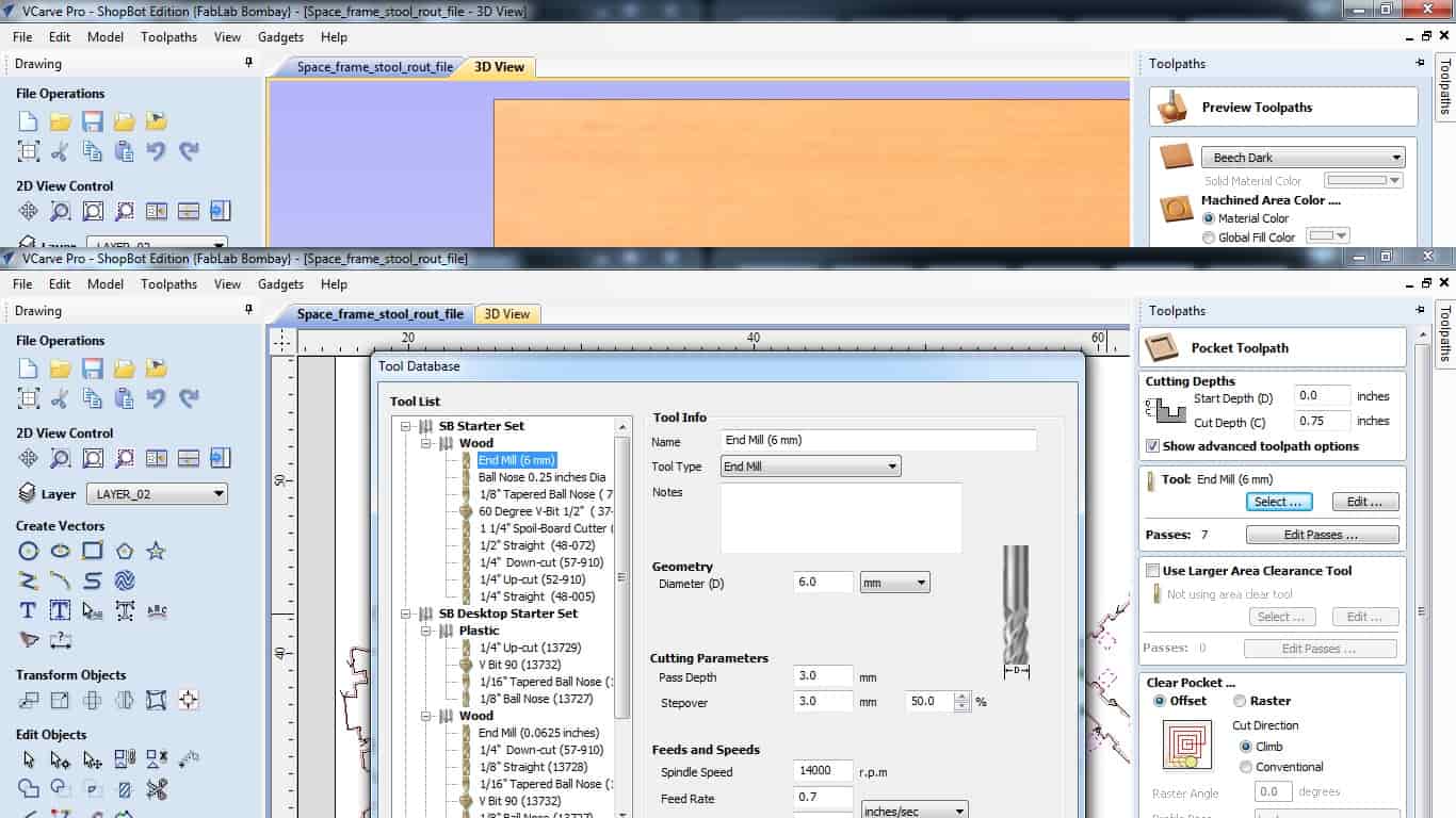
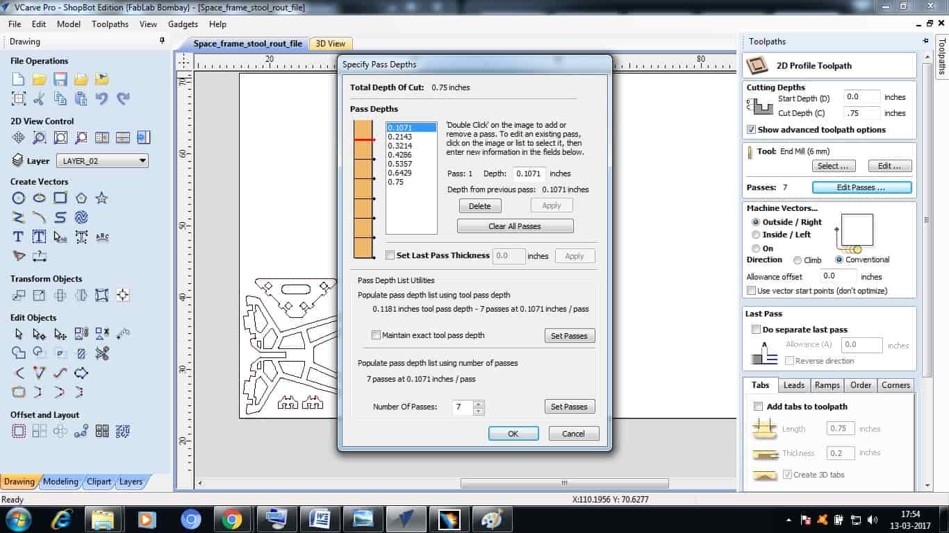
Then comes the main part on VCarve, generating the Tool Part. Tool Path tells the machine how to move the tool to get a perfect job cut. So for every single part in my design I have to mention how the tool should move, how much passes should it take to cut an object without breaking the tool, Tool Size, Speed, etc.
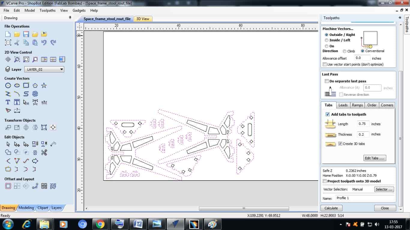
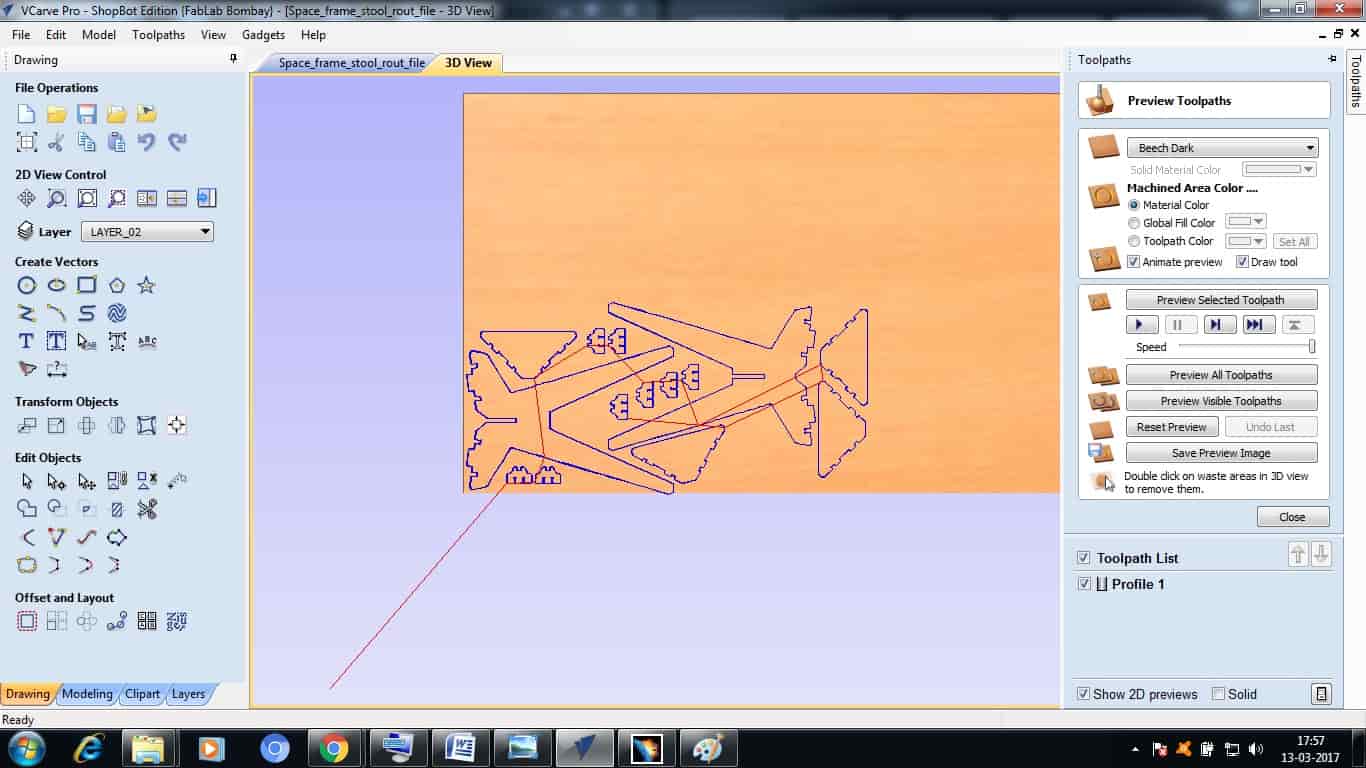
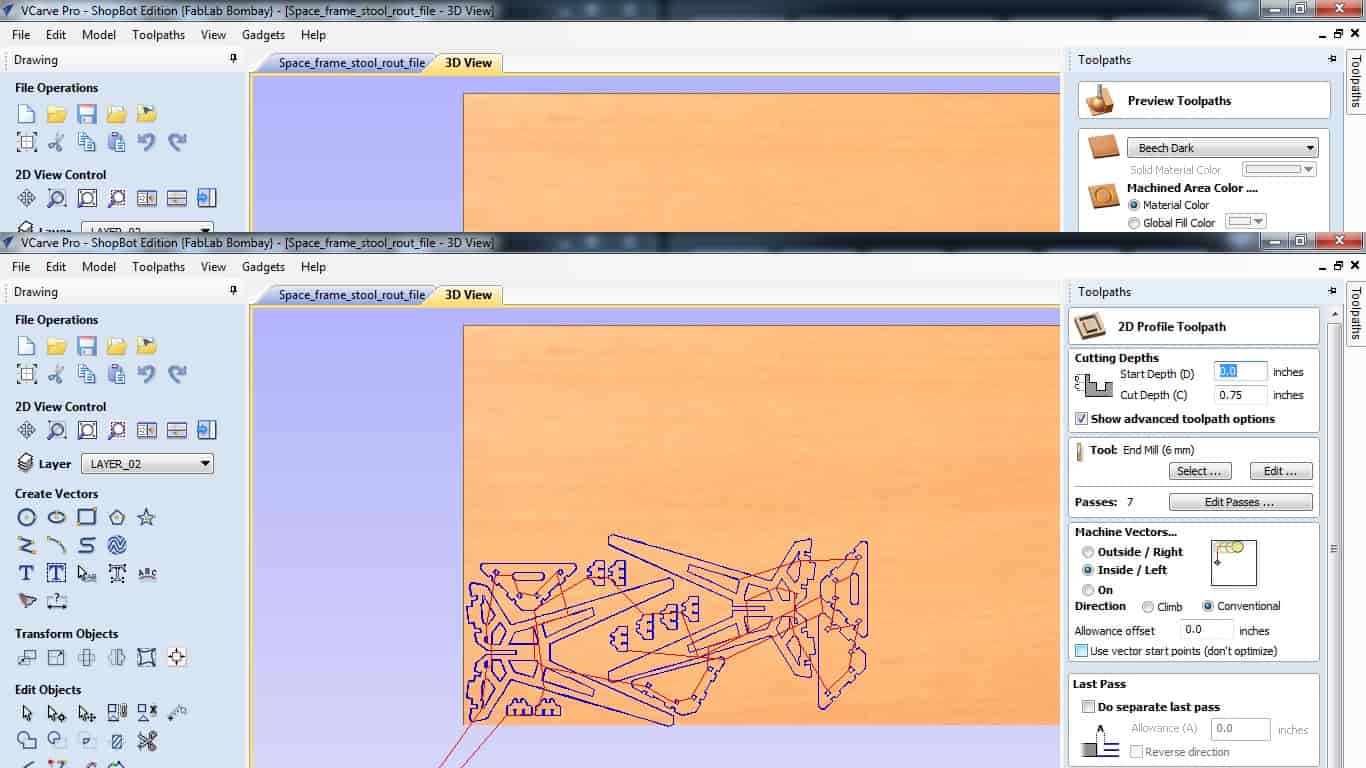
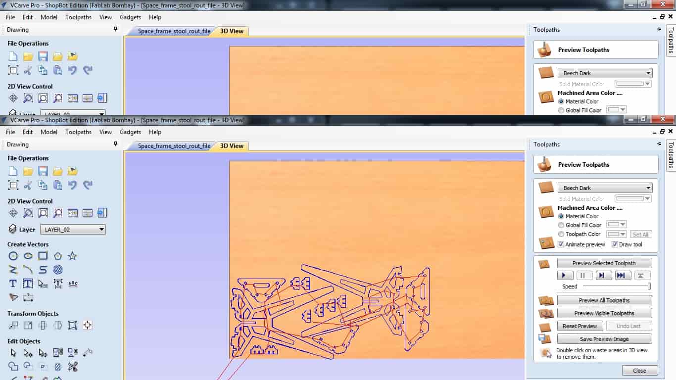
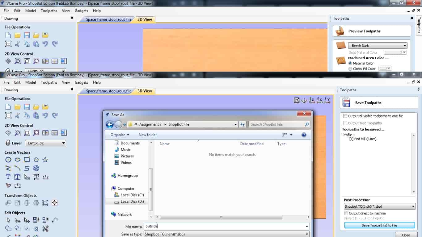
After making toolpath, I was able to see two different views, so in this one shows the 2D design and one shows the 3D design or 3D view how will it be cutting it on machine. So as I was done with the Toolpath, I exported the design file from VCarve to .sbp format, this file will be imported in ShopBot software with which we can start machining the material loaded on ShopBot.
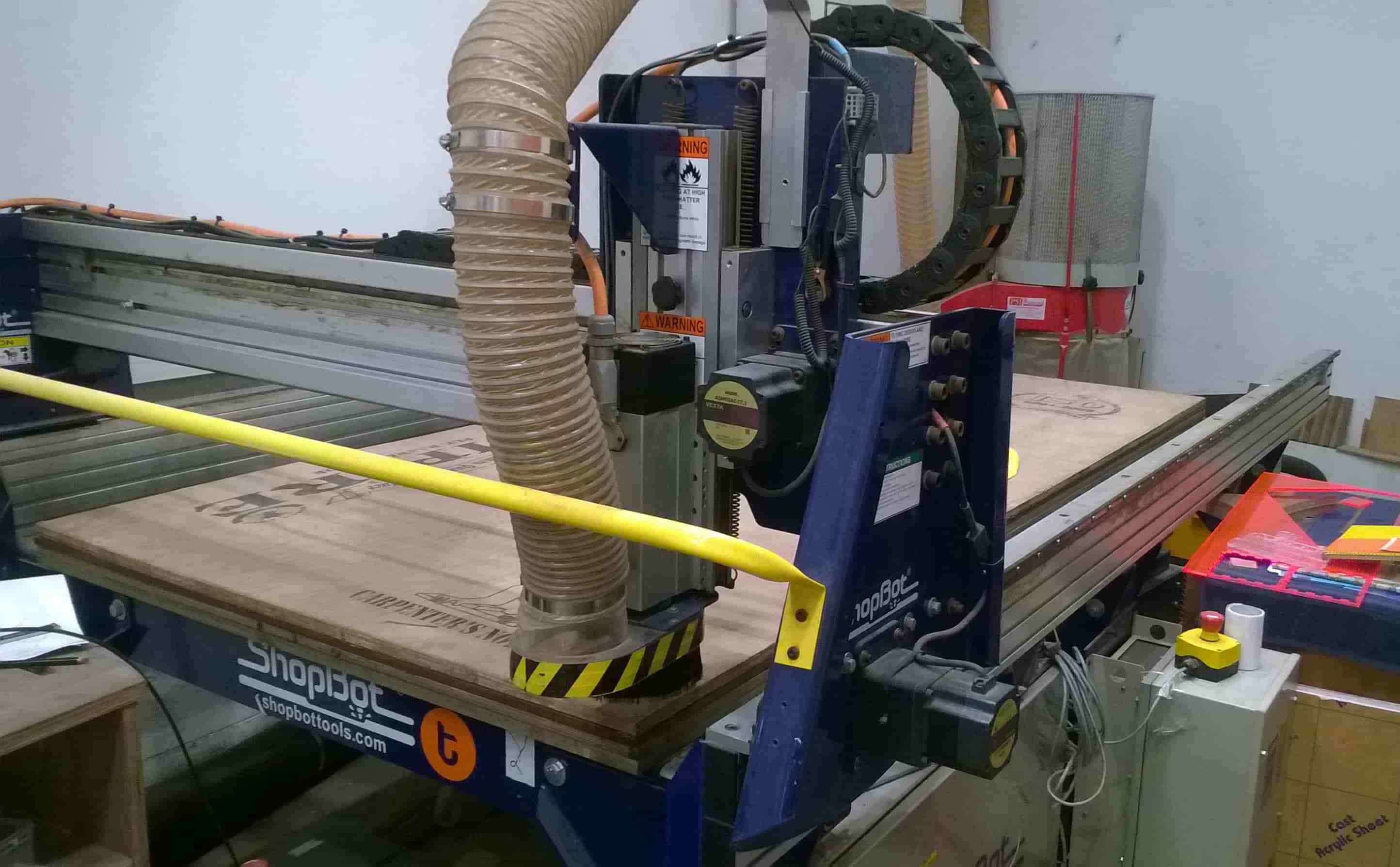
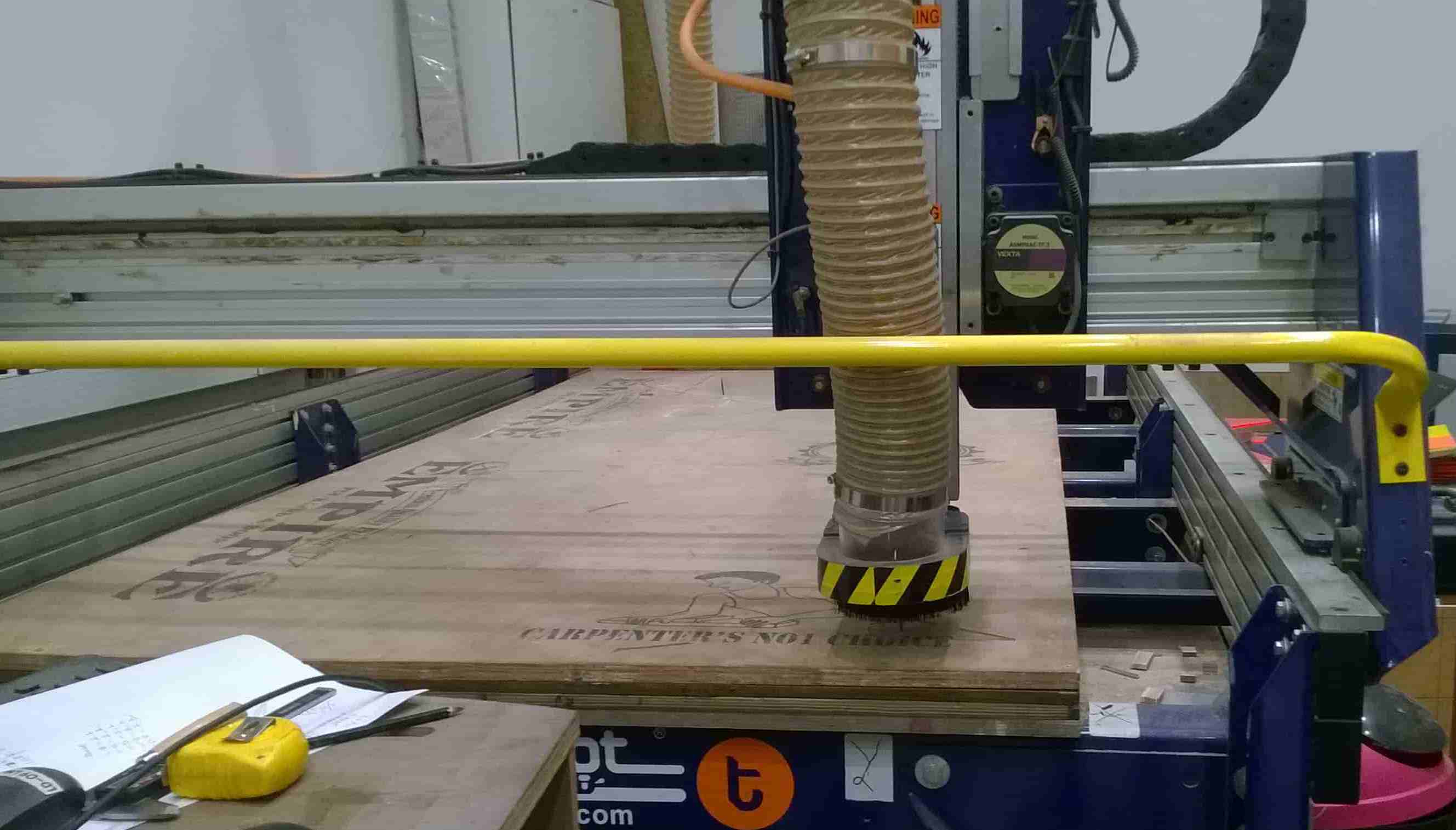
After loading the material on ShopBot, make sure to screw it tightly with the bed so that it should not get disturbed. I then loaded the tool that I generated the tool Path for. I used 6mm tool.
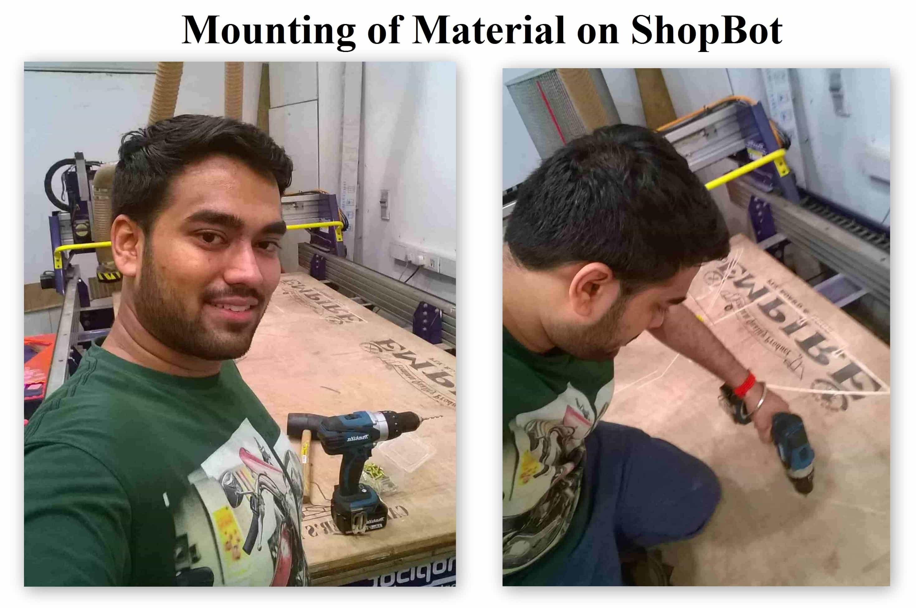
For attaching Bit I removed the dust collector hose to get proper access to tool rack and so that I can attach spanner properly to loose or tight the spindle collet after attaching the Bit.
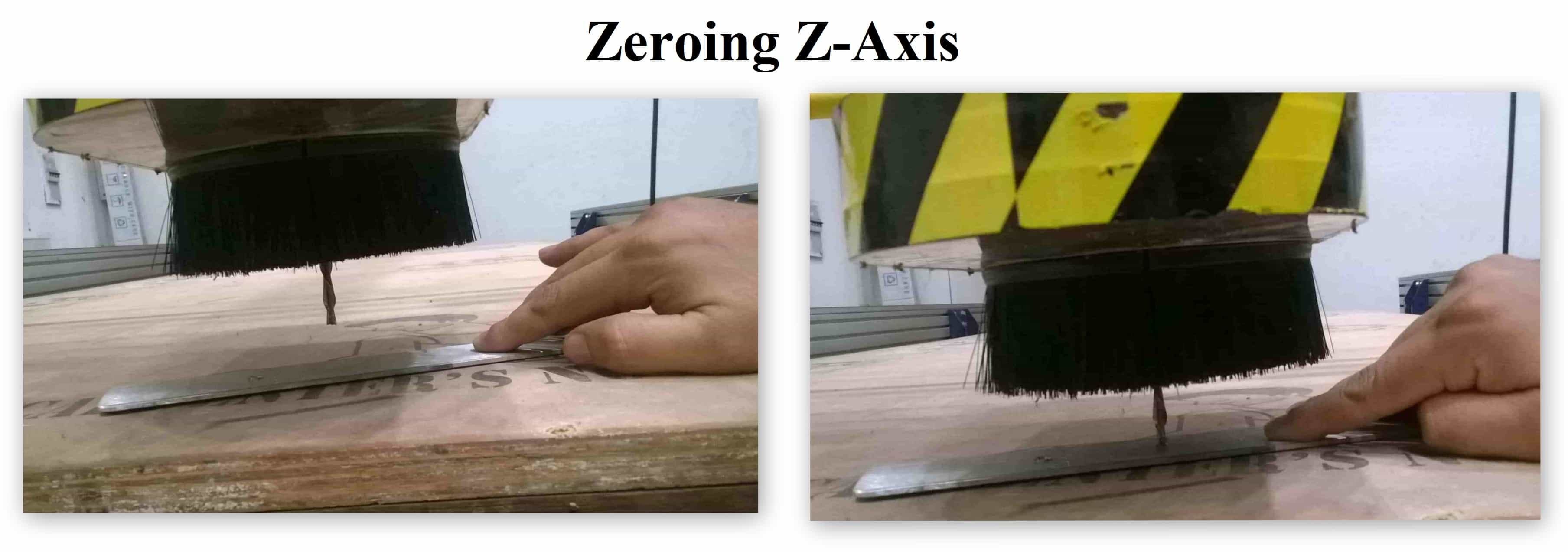
Before starting I then Set the X-axis, Y-axis and Z-axis to zero at a certain place. For setting Z-axis to Zero we need to use the Aluminium plate, as we set the aluminium plate below the Bit and as bit detects the plate it sets its zero there itself. Basically the plate we keep below the tool is connected to the shopbot using the wire which manages to identify the touch of tool with the help of alligator pin attached to that plate and provides feedback to the software.
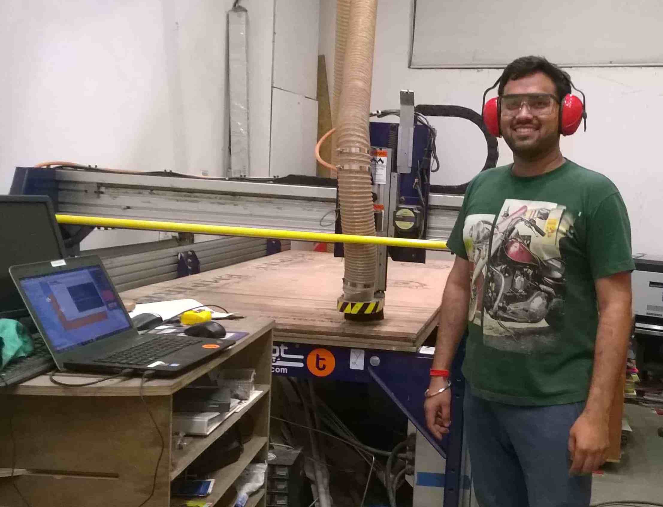
ShopBot in Action
Final Output: